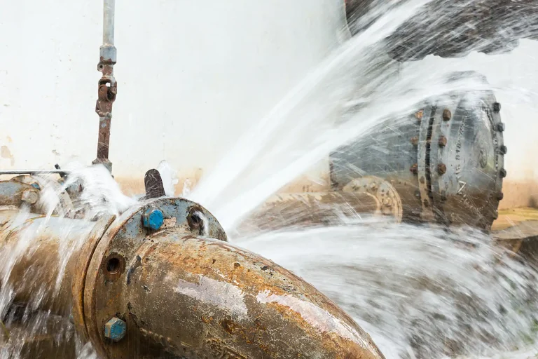
In fire protection piping field practice, the grooved pipe fittings manufacturing process stands as the main factor deciding joint seal performance under service pressure and repeated cycles with no leakage allowed. Jobs on high-rises, data centers, and industrial plants keep shortening timelines while shrinking tolerance for any joint weakness. A small hidden casting issue—shrinkage porosity deep in the section or a gas pore breaking to the gasket surface—shows up as steady drip or sudden burst the instant the line sees pressure. The 2025 NFPA 13 edition, in full force now, permits a C-factor of 120 for dry and preaction systems shielded by vapor corrosion inhibitors or vacuum protection, but that flow reliability only materializes when fittings hold tight from the very first joint assembly.
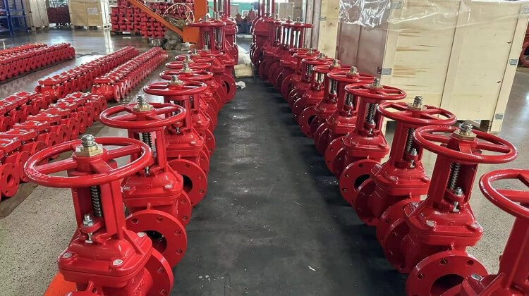
Grooved fittings cover rigid couplings for locked straight runs, flexible couplings for thermal shifts, elbows, tees, reducers, mechanical tees, end caps, and similar pieces. They depend on ductile iron bodies and gasket compression to handle fire pump vibration, minor assembly misalignment, and surge loads typical in sprinkler layouts. The real ongoing work involves wiping out production flaws that weaken body structure or groove accuracy at 2.5 MPa operating levels.
This guide traces the production path that delivers grooved pipe fittings with solid zero-leakage capability in automatic sprinkler service. Emphasis stays on controls that tackle persistent defects including shrinkage porosity, gas pores, cold shuts, and groove dimension drift.
Why Zero Leakage Continues to Matter for Sprinkler System Dependability
Sprinkler networks need instant, even water delivery the second a head trips. Any leakage ahead of activation cuts pressure at far heads, stretches discharge timing, or causes unwanted flow in protected areas like server halls or document vaults. Dry systems, routine in cold-storage or high-value occupancies, face steady internal corrosion that roughens surfaces, drops the Hazen-Williams C-factor, and throws hydraulic calculations off track.
NFPA 13 changes extend the C-120 classification to protected dry and preaction setups, underlining the gain from clean internal walls. Grooved joints have to keep gasket seal against slight angular offset, transmitted vibration, and pressure transients from fast-opening valves. One bad connection can compromise a complete branch or riser.
Fire protection still drives more than half the worldwide grooved fittings demand, with steady growth from commercial towers, distribution warehouses, and institutional projects. Codes tighten field acceptance rules, and owners expect long service with little upkeep. Fittings that truly reach zero leakage cut site rework, limit water-loss claims, and keep systems primed for the activation that counts.
Standard Details: Types, Material Controls, and Pressure Classes
Grooved pipe fittings split into mechanical joints and shaped components. Joints include rigid couplings for axial stability, flexible couplings for movement tolerance, reducing couplings for size changes, angle pad couplings for offset runs, and high pressure couplings. Shaped fittings cover elbows, tees, crosses, reducing tees, reducing crosses, flanges, concentric reducers, end caps, mechanical tees, and mechanical crosses.
Material follows ductile iron QT450-10 grade or above. Ferrite content stays over 85 percent, spheroidization grade hits 3 or better, and the five elements—carbon, silicon, manganese, phosphorus, sulfur—fall within narrow limits. No cold shuts, shrinkage porosity, pores, sand holes, or comparable casting defects appear on surfaces or internally.
Pressure classes divide at 2.5 MPa for grooved connections and 1.6 MPa for threaded connections, matching GB5135.11-2006 for automatic sprinkler applications and compatible with global fire protection standards.
Production Flow: Defect Management from Melt Through Machining
The sequence opens with melting. Pig iron, clean scrap steel, returned iron, recarburizer, and other raw materials charge an intermediate frequency electric furnace in exact ratios. Electric induction coils heat the bath evenly, keeping oxidation and slag low to avoid inclusion sources.
Spheroidization takes place next. The molten batch moves to the processing station, dust removal equipment starts, the cover lowers automatically, and nodularizing wire feeds along the specified line length. Double inoculation distributes graphite nodules uniformly, raising ductility and lowering shrinkage void risks.
Molding pulls from advanced green sand control. Fluid Tech Piping Systems (Tianjin) Co., Ltd. invested 20 million RMB in 2020 to install the Fondarc sand mixing system from France, a setup known for high automation, top efficiency, and stability in the foundry field. This system keeps sand parameters—moisture, permeability, strength—steady to satisfy casting needs. The 416 vertical automatic molding line forms precise cavities with minimal shift or core displacement, maintaining uniform wall thickness and cutting hot-spot formation.
Pouring shifts to automatic machines. Operators dial in flow rate and temperature for smooth fill without turbulence that traps gas or creates shrinkage cavities. Automatic pouring replaces manual ladle work, reducing variation and improving surface soundness.
Following shakeout, runners separate on a scaly line with hydraulic clamps. Operators pull visible rejects early and forward acceptable pieces.
Shot blasting clears sand residue and scale, setting up clean surfaces for machining and coating.
CNC lathes form grooves, threads, and sealing faces to tolerances. Operator self-checks combine with inspector spot checks to catch tool wear or setup drift before batches suffer.
Automated coating applies uniform layers under controlled temperature, speed, and pretreatment, managing daily throughput above 100 tons with reliable adhesion and corrosion protection.
Multi-Stage Quality Checks: Stopping Defects Before They Leave
About one-fifth of the team handles quality across every step. Sand technicians track molding media, lab analysts verify raw and molten composition, metallographers examine microstructures, and inspectors staff stations with overlapping coverage.
Incoming lots face spectral screening for manganese, sulfur, and tramp elements. Off-spec material returns; repeated failures end supplier status. Carbon-sulfur analyzers guide immediate furnace corrections.
Metallographic review covers every melt batch. Samples cut, polish, and inspect under optical microscopes for nodule distribution, ferrite level, and defect detection. Results outside limits trigger quarantine; the standing rule favors scrapping over release.
Furnace-side monitoring with imported analyzers and accurate pyrometers locks composition and temperature. Double inoculation supports even nodule formation and casting integrity.
Sorting zones feature multiple platforms for piece-by-piece inspection. Good fittings advance; defects sort by category to drive root-cause analysis and adjustments.
Air-tightness testing applies to every fitting to expose blisters or porosity paths. Large diameters get 100 percent hydrostatic pressure per standard, smaller sizes see routine sampling to verify zero factory leakage.
Threads check verticality and accuracy with gauges. Batches run first-piece, in-process, and final inspections.
A separate secondary inspection area adds another full layer.
Coating durability confirms in salt-spray chambers for harsh exposure, plus direct thickness and pull-off adhesion tests.
Over 100 instruments—spectral analyzers, infrared carbon-sulfur units, microscopes, tension testers, burst equipment—back the complete inspection sequence.
Fluid Tech Piping Systems (Tianjin) Co., Ltd.: Focused Fire Protection Piping Supplier
Fluid Tech Piping Systems (Tianjin) Co., Ltd., part of Fluid Tech Group since 2018, operates as a specialized provider in northern China for complete fire protection piping packages. Tianjin-headquartered with streamlined warehousing, the company supplies one-stop solutions to contractors globally.
Core products feature ductile iron grooved fittings alongside malleable iron fittings, grooved joints, valves, sprinklers, flexible drops, hangers, and seismic bracing. Exported items hold FM, UL, CE, LPCB, and VDS approvals, with facilities certified to ISO, SGS, and TUV standards.
Quality uniformity stems from standardized procedures, technical guidance, and offerings that align performance with cost realities.
Conclusion
Structured manufacturing combined with thorough verification creates grooved pipe fittings that maintain zero leakage in rigorous fire protection duty. Precise melting, spheroidization, advanced automated molding and pouring, CNC machining, and exhaustive testing—including full air-tightness, hydrostatic validation, and metallographic oversight—remove shrinkage porosity, gas pores, and dimensional flaws that cause field leaks. In 2026, with ongoing priority on hydraulic consistency and reduced upkeep, fittings produced this way give engineers and installers confidence in joint reliability during surges, movement, and extended exposure.
Choosing suppliers that commit to equipment like the Fondarc system, traceability, and uncompromising defect rejection helps deliver fire protection systems that activate reliably when needed most.
FAQs
What causes leaks in grooved pipe fittings used for fire sprinkler systems?
Leaks usually trace to casting defects like shrinkage porosity or gas pores, groove inconsistencies from machining variation, or surface conditions that hinder gasket seating. Full controls—from melt chemistry through 100 percent metallographic batch checks and air-tightness on every piece—eliminate these before fittings ship.
How do manufacturers prevent shrinkage porosity in ductile iron grooved fittings?
Prevention depends on controlled carbon equivalent, double-line inoculation for uniform nodules, automated pouring to limit turbulence, and stable high-strength sand from systems like Fondarc. Metallographic inspection of every melt batch identifies unacceptable spheroidization or defects, leading to immediate isolation.
Why choose ductile iron QT450-10 for grooved pipe fittings in high-pressure fire protection?
QT450-10 provides the tensile strength, ductility, and pressure containment needed for 2.5 MPa grooved service while resisting crack propagation under surge. Ferrite above 85 percent, spheroidization grade 3 or higher, and tight element limits reduce brittle failure and maintain seal reliability.
How is zero leakage verified in grooved couplings before factory release?
Verification involves 100 percent air-tightness testing to detect blisters or porosity, 100 percent hydrostatic pressure on large diameters per code, and routine sampling on smaller sizes. Dimensional gauging and coating adhesion checks confirm no factory leakage.
What stops hidden defects from reaching the job site in grooved pipe fittings?
Progressive checks—spectral analysis of inputs, furnace-front composition monitoring, single-piece sorting at multiple points, secondary re-inspection, and destructive metallographic sampling—catch issues early. Analysis of rejects informs refinements, ensuring only sound fittings proceed to installation.