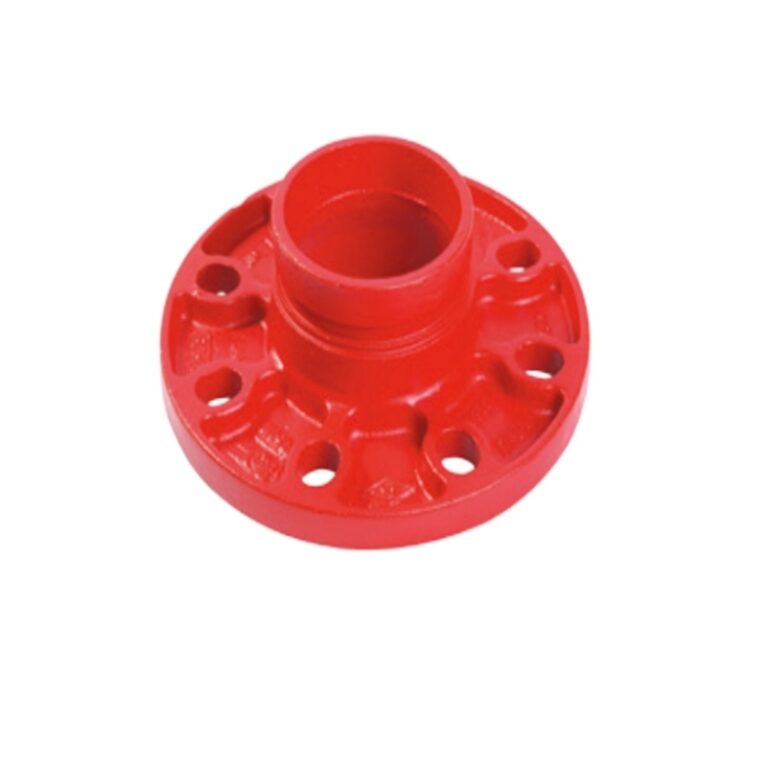
A grooved flange adapter joins grooved pipe to a flanged component such as a butterfly valve. The nominal size gets the review started, but it cannot finish it. The pipe’s outside diameter and groove, the valve’s bolt pattern, the sealing arrangement, and room for the disc and operator all matter. These are drawing checks, and they are most useful before the pipe run is fixed in place.
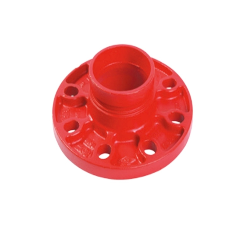
Which adapter listing matches the pipe and valve?
Start with the flange standard in the approved documents. Fluid Tech lists separate ANSI and EN adapters. They follow different flange systems; a familiar DN label does not make their dimensions interchangeable.
Confirm the pipe outside diameter as well as DN
Both product pages describe ductile iron adapters with one grooved end and one flanged end. The ANSI page lists ANSI B16.5 Class 150/300; the EN page lists EN1092 PN10/PN16/PN25. Use the designation specified for the valve and project, not whichever table happens to be easiest to source.
DN50 is a useful example of why OD should be written down. The EN table shows two rows, 57 mm and 60.3 mm; the ANSI table shows 60.3 mm. A drawing for 57 mm OD pipe therefore does not match the ANSI DN50 row. Pause and resolve that discrepancy before ordering. For the ANSI 60.3 mm row, the listed dimensions include L = 65 mm, X = 152 mm, Y = 120.5 mm, and Z = 16 mm. Confirm the table headings and required groove details before using them in a layout.
Check every part of the valve’s flange pattern
Take the flange dimensions from the drawing for the actual valve model: outside diameter, bolt-circle diameter, hole count and size, plus class or PN. Compare each item with the adapter table. Same nominal size is not proof of matching drilling. If the holes do not line up freely, bolts should not be used to drag the parts together.
Check the adapter length against the valve face-to-face dimension and available run length, too. A replacement valve may have a different body length or drilling even when its nominal size is unchanged, so a substitution means repeating the check.
What needs to be settled about the gasket and pressure rating?
Once the metal dimensions agree, the gasket detail and component ratings still need an answer. Keep the documents for the adapter and valve together; the joint depends on instructions for both selected models.
Follow instructions for the specific models being joined
Fluid Tech’s adapter information calls for cleaning the pipe groove and flange sealing face, positioning the gasket correctly between the flanges, and tightening bolts evenly. Check the valve instructions as well. They should clarify whether a separate gasket is needed and where it sits. A note for another valve series cannot answer for the model on this submittal.
An extra gasket can alter face spacing or project into the opening; omitting one required by the valve instructions can compromise the joint. If the arrangement is unclear, raise it in the submittal review while the parts can still be changed easily.
Treat the ratings as component-specific
On the product pages, the ANSI adapter has listed pressure options of 1.6 and 2.5 MPa; the EN adapter lists 1.0, 1.6, and 2.5 MPa. Both show -20 to 120 degrees C. Those figures belong to the adapter listings, not automatically to the completed assembly. Verify the selected valve, gasket, coupling, and pipe against the project conditions using each component’s own documents.
How can disc and operator clearance be checked?
Even a correctly drilled flange can leave a valve that cannot operate freely. The layout review needs to account for the moving disc and the space needed around its operator.
Review disc travel using the valve drawing
Use the drawing for the selected valve and follow the disc through open and closed positions. Check its edge against the adapter opening, gasket, pipe end, and nearby fittings. Shape and clearance depend on the model and size; a product photograph will not settle this check.
Keep the checked drawing with the submittal. A model change calls for a new review of disc dimensions, even if the flange size stays the same.
Leave space to operate and service the valve
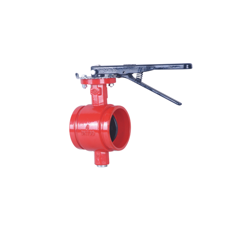
A lever has a travel arc. A gear operator or actuator needs service access. Mark the planned orientation and look for conflicts with ceilings, walls, insulation, supports, access panels, and adjacent valves. Fluid Tech lists a grooved-end resilient-seated butterfly valve as another product option. Its grooved ends serve a different connection arrangement from the flanged valve considered here.
What should be checked when the parts arrive?
At receiving, compare the part markings with the approved submittal. Lay out the pipe, coupling, adapter, gasket, and valve as one assembly. If a groove, bolt pattern, or model reference differs, stop and settle it before tightening.
Assemble according to the selected product documents
Clean the groove and sealing face, place the gasket as specified, and tighten evenly. Use the instructions supplied for these models; values taken from another product are not a substitute. Check valve movement and interference, then carry out the project tests named in the approved documents.
The grooved flange adapter range shows the listed ANSI and EN options. FLUID TECH PIPING SYSTEMS supplies piping products for fire protection applications. For a supplier enquiry, send the adapter standard, pipe OD and groove, valve model or drawing, and required pressure designation. That gives the team a concrete combination to review; compatibility still comes from the approved design and selected product instructions.
Conclusion
Before connecting a butterfly valve, verify the adapter standard, actual pipe OD and groove, complete bolt pattern, gasket arrangement, component ratings, and operating clearance. ANSI and EN tables represent different configurations; nominal size alone does not establish compatibility. Keep the drawings and instructions for the selected models together and resolve any mismatch before installation.
FAQs
Will any grooved flange adapter fit a butterfly valve of the same size?
No. The adapter’s flange drilling and sealing arrangement must match the exact valve, and its grooved end must suit the pipe and coupling. Check both ends against current product documents.
Should a separate gasket always be installed between the adapter and valve?
No. Follow instructions for the exact adapter and valve models. An extra gasket may change spacing or affect the opening, while omitting a required gasket may compromise the joint.
Why check actual pipe OD when the nominal DN is correct?
Some tables list more than one outside diameter for a nominal size. The EN adapter table, for example, shows DN50 entries for both 57 mm and 60.3 mm OD, so the measured or specified pipe OD determines which row applies.