A schedule entry reading “2-inch test and drain valve” looks precise, but it leaves out the test orifice. The connection size tells the supplier how the valve joins the pipework. It does not necessarily identify the opening used for testing. For a usable quotation, record both values and explain what the test point is intended to do. Thread details, access, and the discharge route belong in the same review.
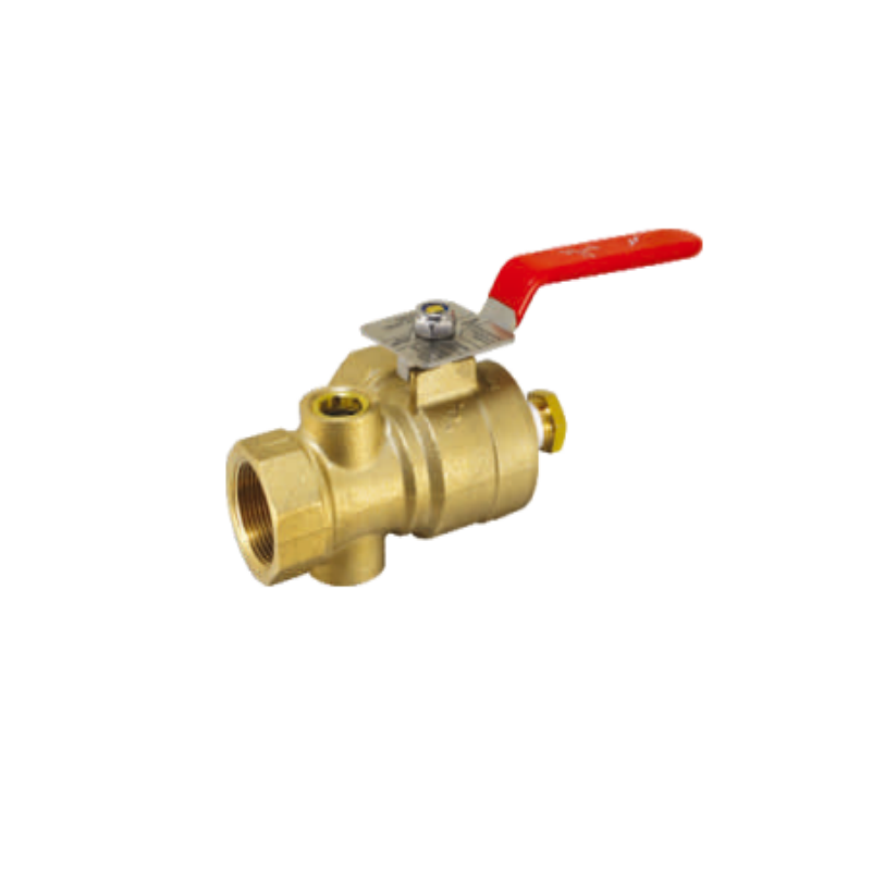
What work will the valve perform at this location?
Fluid Tech describes its test and drain valve as combining controlled drainage with testing of pressure switches or flow alarm devices. The name covers more than one activity, which is why the drawing and commissioning procedure belong beside the catalogue when selecting it. They explain what is expected at this particular location.
Identify the point on the drawing
“Test valve” may be adequate shorthand in a conversation with the designer. For someone preparing an offer, it leaves the intended task open to interpretation. Put “flow alarm test,” “drainage,” or both against the relevant drawing location. There is then a specific detail to refer to if a question comes back about that line item.
The sight of water at the outlet isn’t the whole test. Whether the required alarm response has occurred, and what needs recording, comes from the project procedure. The commissioning team needs those approved instructions, not just the product description supplied with the order.
Why should the body connection and orifice be listed separately?
There are two questions hidden in the word “size”: what piping will connect to the body, and what opening is provided for the test? Give each its own column. The person reading the schedule can then see both values without interpreting a note written for another purpose.
Read across the product table
Fluid Tech’s table lists 1-inch, 1¼-inch, and 2-inch connection entries alongside a ½-inch orifice. Several body connections therefore appear with the same test opening. Read across the selected row and carry both values into the offer, rather than leaving one to be inferred from the other.
For a design that calls for a defined discharge, there is still a hydraulic question for the designer to resolve using the relevant product information. Choosing a body connection doesn’t settle it. A blank in the orifice column should come back as a request for clarification before purchase, not disappear into an assumption at order entry.
Will the offered valve connect to the specified pipework?
The expected size label can appear on a valve that has the wrong interface for the job. Looking at the offered drawing beside the installation detail makes the thread and port arrangement easier to compare, before either becomes a problem on site.
Name the thread standard
An enquiry that says only “threaded” hasn’t identified a thread standard. That gap matters when documents from different markets are being used together. Write out the standard and the sizes of both connections. If the pipe route depends on the positions of the ports, the supplier’s dimensional drawing is the place to check them.
The project schedule remains the reference for materials and pressure requirements within the fire valve control system. With approvals, the useful question is which model and sizes the document covers. A general mention of UL or FM in a catalogue isn’t the answer to that question. The submission needs evidence tied to the item offered.
Allow space for someone to operate it
For a valve above a ceiling, look at it from the hatch. Is the handle within reach, and can it turn without meeting another service? The operator also needs a view of the markings and connections. A drawing may show plenty of space around the body while leaving someone reaching awkwardly past another pipe to use it. Allow for that task when reviewing the position.
The coordinated drawing is where nearby services can be seen together. If the valve moves during that coordination, its access needs another look too. An earlier clearance check belongs to the earlier position.
Is there a discharge route at the proposed location?
You should be able to follow the outlet to its receiving drain on the fire sprinkler system drawing. If the route stops at the valve symbol, that part of the arrangement still needs resolving. The valve schedule may say little about where discharged water is meant to go.
Look beyond the valve symbol
With the receiving drain marked, the reviewer can compare the proposed route with the site. An installation photo from elsewhere can illustrate how a product is arranged, but the drainage route in that photograph belongs to that building. It doesn’t establish an available route here.
One drain point cannot be assumed to empty every branch. Follow the piping past any low points when checking what can drain toward this valve. The approved design and product instructions remain the installation and operating references. A revised pipe route deserves another look at the drain arrangement too, even if the valve itself hasn’t changed.
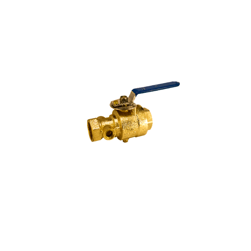
What should buyers send Fluid Tech for a quotation?
The valve can be sourced alongside related pipeline and sprinkler components from FLUID TECH PIPING SYSTEMS (TIANJIN) CO., LTD. Its one-stop procurement service lets buyers include those products in the same enquiry. For this valve, send the marked installation detail as well as the schedule, so the connections can be seen in context.
In the request, write down the intended test and the orifice called for by the design, followed by the inlet, outlet, and thread details. Add quantities and the documents needed for review. If one value is awaiting confirmation, say so. Ask Fluid Tech to return the connection and orifice as separate entries in its quotation. That gives the reviewer a direct comparison with the drawing and leaves a clear specification to carry into the order.
Conclusion
The body size is only one entry on a usable test and drain valve specification. The test opening has to be identified too, with a drawing that accounts for the connections, access, and discharge. An offer based on that information can be checked against the project detail rather than against a product name alone.
FAQs
Does “2-inch” describe the test opening?
It may describe the body connection instead. The Fluid Tech table pairs several connection sizes with a ½-inch orifice, so both dimensions belong in the selected product description.
Is a drain-only valve an acceptable alternative?
That needs a design review. A drain-only offer may omit the test function intended at this point. The approved detail and procedure determine whether the alternative is suitable.
Which approval documents should accompany the offer?
Use the project’s document requirements. Where an approval is specified, the evidence needs to cover the actual model and size in the offer; company-level statements aren’t enough to establish that coverage.